
LUFKIN Well Manager™ 2.0 Upgrade Kit
Easily upgrade all first-generation LUFKIN Well Manager Controllers.

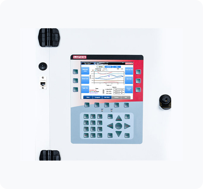
The next generation of rod pump control developed to easily install in all first-generation LUFKIN Well Manager controllers.
The LUFKIN Well Manager 2.0 (LWM 2.0 ) upgrade kit provides the new enhanced functions and processing power of the LWM 2.0 to be effortlessly installed in all existing first-generation LWM enclosures with minimal downtime.
Features
- Custom-designed conversion package of equipment to upgrade existing LWMs
- Full next generation LWM 2.0 control capabilities
- Simple and intuitive interface
Advanced Control Capabilities At Your Fingertips
More than a rod pump controller, the LWM 2.0 features advanced control functions, including Variable Speed Pump-Off Control, Fluid Pound Avoidance, Torque Functions and Pump Tag Mitigation to optimize production in dynamic conditions. Pump-Off Control can be configured to utilize pump fillage or live or calculated pump intake pressure as a setpoint.
Minimize Risk of Early Equipment Failures, Extend Uptime
Advanced functions such as gear reducer torque and pump tag monitoring provide the operator with the tools to quickly verify that the pumping system is operating within its operating limits, minimizing the risk of early equipment failures.
Additional Advanced Functions:
→ Intra-Stroke VSD Fluid Pound Mitigation
→ Pump Tag Mitigation
→ Scheduled Pump Card Pattern Matching Analysis
Additional Advanced Functions:
→ Intra-Stroke VSD Fluid Pound Mitigation
→ Pump Tag Mitigation
→ Scheduled Pump Card Pattern Matching Analysis
Increased Flexibility, Multiple Communication Modules
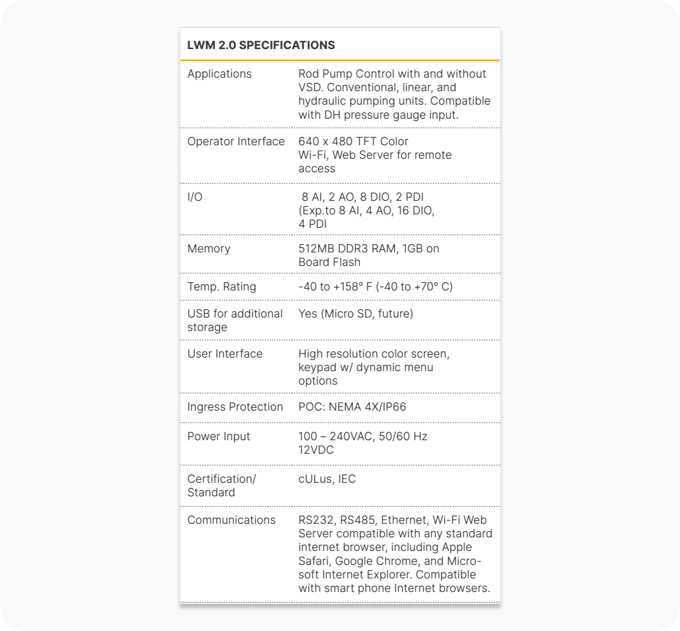
The modular design of the LWM 2.0 provides easy field service solutions and includes a communications module complete with multiple Ethernet ports, RS-232, RS-485, and Wi-Fi communications. In a SCADA environment, Modbus RTU and TCP are supported in both master and slave configurations. Connectivity via Ethernet is fully supported. Dynamic Modbus Register Configuration functionality provides the operator with the flexibility to design a most efficient SCADA system.
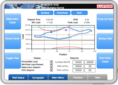
VSD Control Function
Intuitive dynagraph setup with permissible loads
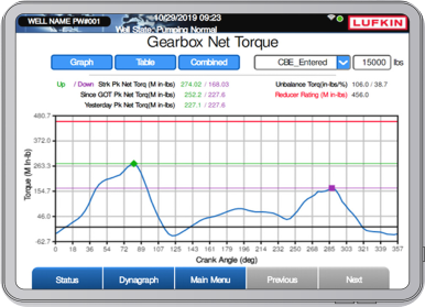
Gear Reducer Torque
For every stroke, the LWM 2.0 calculates gear reducer torque per 15 deg. Crank Angle intervals utilizing actual Polished Rod Load utilizing the API RP11E method. A VFD is not required to generate the torque plots!