Rod Pump is one of the most used artificial lift systems worldwide nowadays due to reliability, robustness, durability, production ranges and low cost when compared to other systems. The versatility of rod pump lies in the possibility of applying it in heavy, medium or light crudes in reservoirs with relatively low pressures.
However, although rod pump has great advantages that make it applicable for many reasons, it is necessary to evaluate the criteria of its application before installing it, such as: its susceptibility to high gas ratio, sand production, pump depth installation, deviation degree and geographical location of the well.
Once all the previously mentioned factors have been taken into account, and after the rod pump system has been installed, the optimization process is very important, since not doing it properly, this could lead to a significant increase in operating costs.
It is important to remember that it is the artificial lift system that adapts to the well and not the other way around. When we talk about production optimization, there are important considerations to take into account when designing such as the expected production rate, the properties of the fluids to be handled (viscosity, solids content, water and gas content, salinity, presence of H2S), pump depth, geometry of the hole, oil gas ratio, among others.
In the design of a rod pump lift system many considerations may be ignored or reduced. Even many simulators put aside very important operational factors due to the lack of any correlation that may take into consideration very important data necessary to adapt a hypothetical case as much as possible to a real case of any well that is the object of design.
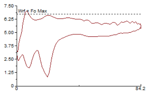
Some authors comment that in a rod pump design, the ideal dynamic chart is that obtained with the well operating at a speed such that the dynamic chart is 100% full and always maintaining the fluid level closest to the pump intake, resulting in something similar to what is shown in figure 1.

Figure1: Ideal dynagraphic pump chart.
But in a real system in which the flow pattern is not uniform, in which the fluid is not single-phase and in which the operational and reservoir conditions are changing, maintaining this filling condition in the pump is not an easy thing to achieve. In any case, the intention is to try to keep the system optimized without generating major disturbances or significant changes in operating conditions.
When carrying out corrective actions for one reason or another, it is always advisable to make changes (deplete resources) on the surface before making them at the subsoil level. This as long as the facilities allow it. In rod pump, one of the the most helpful resources to optimize the system is the pumping speed. However, many times when using beam-pumping units, there are no devices to vary this condition in this type of units, so only the resulting direct velocity between the engine RPM, the pulley ratio and the rocker gearbox is counted. So, how to generate speed changes for example in a system like this? Imagine also that the dynagram in this case is the one shown in figure 2.

Figure 2: Dynamic chart with fluid pound.
From a chart like this, certain hypotheses could be generated, taking into account the current evident condition of fluid pound because the well could present a low fluid level. For this reason, to try to maintain a complete pump fillage, either the stroke length of the unit or the pumping speed could be reduced. Another more expensive action would be to perform an intervention with a hoist to install a pump of smaller diameter or look for a greater depth of settlement. Now, let´s suppose that the pump is sitted at 3,000 feet deep and a study reveals that the fluid level is at 500 feet. That is, the pump would have 2,500 feet of submergence.
This condition would dispel a low submergence hypothesis, so we could conclude to be observing a partial fillage of the pump. Then a well with a dynagram and submergence like this could be presenting another condition such as high speed operation, which would be preventing an efficient filling of the pump. If a device that allows to vary the pumping speed to execute a reduction of the same one is not available, it could be studied to change the pulleys ratio through the change of diameters of the motor pulley (reduction) and the pulley of the beam unit gearbox (increase), which would reduce the operating speed, that even though it might not be enough, would bring an improvement to the system in places where resources are limited.
The ideal speed of operation is a very important factor to consider, since the damages that could be generated in the system due to tension and compression phenomena in the rod string as well as the flotation of the same, product of unsuitable speeds, could generate fatigue in the rest of the components of the system, which can cause subsequent damages to the surface or bottom equipments.
In some cases the interpretation of a dynamic chart is quite easy, however in others the diagnosis can be quite complicated to determine, there is even the possibility of not obtaining the dynagram in those wells that present severe rod string flotation.
As we can see, there are countless cases that could be presented for each well. They can be caused by different reasons and it will depend on the experience of each professional to give correct interpretation and solution to each case. The most advisable always when diagnosing each scenario is to rely on the largest amount of information available in order to make an accurate recommendation. The sequence of historical dynagraphic charts, fluid level records, previous work overs, repairs, run life of the equipment, operating speeds, bottom and surface pressures, length of pump travel, etc. are very important data in the optimization process.

