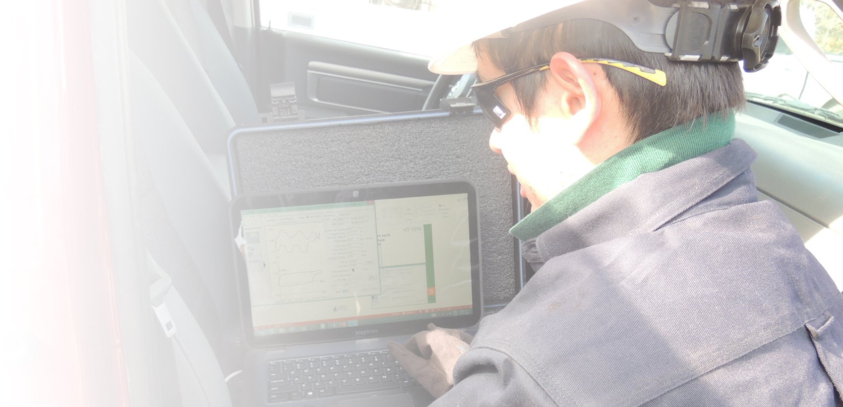
During normal operation, the Well Analyzer is connected to the Remote Fire Gas Gun by two cables.
The larger multi-conductor cable supplies power to the pressure transducer and receives electrical signals from the pressure and temperature sensors. In addition, the larger cable supplies 12-volt power to the electrical solenoid for approximately 1 second to actuate the solenoid. The solenoid should actuate and cause a gas valve to open and allow gas to escape from the gas gun volume chamber into the well. If a question exists about the gas gun generating a sharp acoustic pulse, shoot the gas gun into the atmosphere and verify that the gas gun is operating properly. A definite gas pulse explosion should be heard when the gas gun is charged to 500 PSI, then fired into the atmosphere. The gas gun may need to be cleaned and lubricated before the gas gun will generate a good pulse. The internal gas valve must be lubricated for smooth and proper operation.
The acoustic pulse generated by the gas gun should be released into the well through a full opening 2" conduit for best results. The distance between the gun and the well should be less than 5 feet for optimum results.
The acoustic pulse should be strong for optimum performance. Normally, the gas gun volume chamber is charged to 200 PSI in excess of well pressure for the initial test. More or less gas pressure can be used after satisfactory results are obtained with either more or less pressure.
The gas gun microphone detects the shot when the gas pulse "hits" the microphone disks. This large pressure pulse generates a large electrical signal that indicates that the shot pulse has been generated and has started traveling down the well. The signal from the microphone travels through the electrical connector on the gun, through the 90-degree swivel connector on the gun (if present) and through the single conductor cable to the Well Analyzer. The biggest cause of non-detection of the initial shot pulse is non-continuity of the wiring between the microphone and the Well Analyzer. Inspect all electrical fittings and the cable to insure that the wiring is continuous between the microphone and the Well Analyzer. The inner contacts on the cable and other fittings must be in good shape. Most of the contacts are gold plated, but the contacts must be clean for electrical continuity. Clean with alcohol or a good contact cleaner if needed.
The operator can view the acoustic background noise in the well before the gas gun acoustic pulse is generated to determine liquid level depth. If the electrical connection is proper between the gas gun microphone and the Well Analyzer, a tap on the gas gun will cause a response in the acoustic trace. This is verification that electrical continuity exists between the microphone and the Well Analyzer.

